
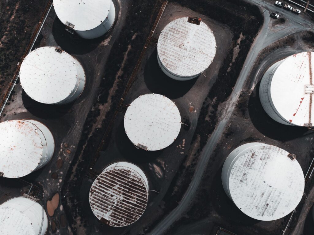
A slop tank is a dedicated vessel that collects off-specification hydrocarbon, oily water and tank drainings so the mixture can be settled, treated and recovered rather than sent to disposal. It functions as both buffer storage and a first-stage separator. How well it performs the second role depends almost entirely on interface control — the management of the emulsion band that forms between the oil and water layers.
Most slop tanks that are “full” are not full of slop. They are full of rag layer.
What a slop tank does
Three jobs, in order of how often they are done well:
Buffering. Absorbing intermittent off-spec streams so upstream units are not constrained. Nearly every slop tank does this adequately.
Gravity separation. Allowing free water to drop and free oil to rise. Most tanks do this partially.
Emulsion resolution. Breaking the stabilised band in the middle. Most tanks do this poorly or not at all, because it requires chemistry and heat rather than time.
A slop tank without a treatment strategy is a tank that slowly converts into a rag layer store.
Anatomy of the tank contents
From top to bottom, a settled slop tank contains:
| Layer | Composition | Typical depth | Disposition |
|---|---|---|---|
| Vapour space | Hydrocarbon vapour, inert gas | — | Vapour recovery / breathing |
| Clean oil | Free hydrocarbon, low BS&W | Variable | Skim to recovery or crude charge |
| Rag layer | Stabilised water-in-oil emulsion, fine solids, asphaltenes | 0.2–2 m, grows over time | The problem — requires treatment |
| Free water | Process water, brine, condensate | Variable | To effluent plant |
| Sludge / bottoms | Settled solids, heavy hydrocarbon | 0.1–1 m | Periodic cleanout |
The rag layer is the operational metric that matters. A stable, thin rag means the tank is working. A thickening rag means chemistry, temperature or feed segregation has drifted.
Why the rag layer grows
Every batch of untreated slop entering the tank contributes stabilising material — fine solids, asphaltenes, naphthenates, residual production chemicals. If the resolution rate is lower than the accumulation rate, the band thickens. Because the rag sits between the two draw-off points, thickening reduces both clean oil capacity and water draw simultaneously.
It also ages in place. The longer the emulsion sits, the more the interfacial film cross-links and the more the solids consolidate. A rag layer left for a year needs substantially more chemistry than the same material treated within a month.
Interface control in practice
Measurement
You cannot manage what you cannot see. Interface detection options:
- Manual dipping with water-finding paste — cheap, reliable for the oil–water interface, blind to the rag layer’s extent
- Guided wave radar — detects distinct interfaces but can be confused by a thick, diffuse emulsion band
- Capacitance / RF admittance probes — profile the transition zone, better at showing rag thickness
- Interface profilers — give a genuine density profile through the depth, the most useful for rag management
Sampling at multiple depths remains the ground truth. Profile quarterly at minimum, monthly if the tank is under active treatment.
Temperature
Heating to 60–90 °C reduces viscosity and increases droplet mobility. Steam coils or external heat exchangers are typical. Two cautions: excessive local heat at the coil promotes coking and fouling, and heating a tank with light ends present raises vapour management concerns. Uniform, moderate heat beats aggressive local heat.
Chemical treatment
This is where rag layers are actually resolved. A slop oil demulsifier selected against a sample of the actual rag — not the clean oil above it — destabilises the interfacial film and allows coalescence.
Practical dosing considerations:
- Inject into the rag, not the surface. Chemistry applied to the top layer has to migrate down through oil to reach the interface. Dedicated injection at rag depth, or injection into the recirculation line drawing from that depth, is far more effective.
- Recirculate. Gentle circulation distributes chemical and provides the mild shear that promotes droplet collision. Excessive shear re-emulsifies — this is a real risk with high-speed pumps.
- Dose to the rag volume, not the tank volume. Slop demulsifier dose rates are commonly 100–1,000 ppm on treated volume, well above production demulsifier rates, because the emulsion is dirtier and older.
- Re-test seasonally. Feed composition drifts with crude slate, weather and turnaround activity.
Feed segregation
The single highest-leverage change at many sites, and it costs nothing chemically. Routing easy streams — off-spec light product, clean condensate — away from the tank receiving desalter rag and tank bottoms means the difficult material no longer contaminates the easy material. Two smaller tanks with different treatment regimes usually outperform one large tank treated to the hardest common denominator.
Common operating problems
Rag layer creeping upward into the oil draw. Recovered oil BS&W rises and the crude unit rejects the stream. Cause: resolution rate below accumulation rate. Fix: dedicated rag treatment campaign, then a maintenance dose.
Oil carryover to the water draw. Effluent plant sees elevated oil-in-water. Cause: water draw too high, or emulsion extending below the interface. Fix: lower the draw, add a deoiler on the water side.
Solids accumulation reducing working volume. Cause: no mechanical solids removal route. Fix: scheduled decanter campaigns rather than infrequent full cleanouts.
Emulsion returning after apparently successful treatment. Cause: fresh untreated feed, or shear from transfer pumps re-emulsifying resolved material. Fix: continuous low-rate dosing on the inlet, and review pump selection.
Frequently asked questions
What is a slop tank on a ship?
Under MARPOL Annex I, a slop tank holds oily residues from cargo tank washings and machinery space drainage. Contents are logged in the Oil Record Book and discharged only to approved port reception facilities.
What does slop tank mean in a refinery?
A vessel collecting off-spec hydrocarbon, tank drainings and separator recoveries for settling and treatment before the oil is reblended into the crude unit charge.
How do you remove the rag layer from a slop tank?
Heat the tank to 60–90 °C, inject a slop-specific demulsifier directly at rag depth, recirculate gently to distribute the chemistry, then draw the resolved water and skim the recovered oil. Persistent rag with high solids also requires mechanical separation.
How often should a slop tank be cleaned?
Full cleanout intervals vary from 3 to 10 years depending on solids accumulation. Sites running an active chemical and decanter programme extend intervals substantially because solids are removed continuously rather than accumulating.
What temperature should a slop tank be held at?
Typically 60–90 °C. Higher temperatures improve separation but increase vapour management concerns and coil fouling risk.
Where to go next
Rag layer thickness is the clearest indicator of whether a slop tank is working as a separator or merely as storage. Reversing a growing rag needs chemistry matched to the rag itself.
Rodanco screens slop oil demulsifiers against client rag samples in our laboratory, and our field team sets injection points and dose rates on site.
See our full approach to slop and waste stream treatment.
Rodanco B.V. is a Netherlands-based specialty chemicals supplier serving oil, gas, fuel and industrial cleaning operations across Europe.
Related articles
References
- Recycle of oily refinery wastes — slop oil treatment tank phase separation and middle-layer behaviour. US Patent and Trademark Office. https://image-ppubs.uspto.gov/dirsearch-public/print/downloadPdf/5009767
- Techniques for treating slop oil in the oil and gas industry: a short review. Fuel, ScienceDirect. https://www.sciencedirect.com/science/article/abs/pii/S0016236120314782
About this article
Written by the Rodanco technical team. Rodanco B.V. operates an in-house laboratory in Alkmaar, the Netherlands, running screening, compatibility testing and tailored formulation work, and a field service team conducting on-site trials and dosing optimisation across European and global energy markets.
Standards notice. Values quoted from CEN standards are given for guidance. Standards are periodically revised and national annexes differ. Always verify against the current published edition before contractual or specification use.
Last reviewed: August 2026